Bedienungsanleitung Rangierhilfe Titanium
Nr. 356280
PC: BER201097621
REMOTE CARAVAN MOVER Installation Guide and User Information
Model No. EGO400 – Rangierhilfe Titanium
QTR-M004-BER

Please visit www.purpleline.co.uk/caravan-movers before installation to check for any updates on product specifications, usage, safety or installation instructions.
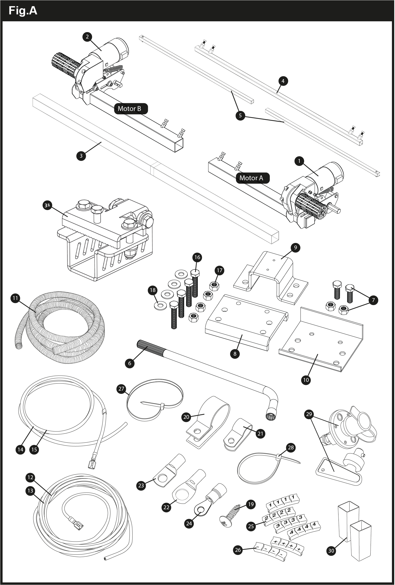
Package Contents (Fig.A)
| Reference | Quantity | Description |
|---|---|---|
| 1 | 1 | Motor Unit (A) |
| 2 | 1 | Motor Unit (B) |
| 3 | 1 | Main Cross Bar |
| 4 | 1 | Cross Actuation Centre Bar |
| 5 | 2 | Cross Actuation Insert Bars |
| 6 | 1 | Engagement Tool |
| 7 | 4 | Classic Clamp – Stop Nut and Bolt * |
| 8 | 2 | Classic Clamp – Upper Plate * |
| 9 | 2 | Classic Clamp – U Plate * |
| 10 | 2 | Classic Clamp – Lower Plate * |
| 11 | 1 | Convoluted Cable Trunking |
| 12 | 2 | Positive (+) Red Motor Cable |
| 13 | 2 | Negative (-) Black Motor Cable |
| 14 | 1 | Positive (+) Red Battery Cable |
| 15 | 1 | Negative (-) Black Battery Cable |
| 16 | 8 | Classic Clamp – M10x55 Bolt |
| 17 | 8 | Classic Clamp – M10 Nyloc Nut |
| 18 | 8 | Classic Clamp – Ø10mm Washer |
| 19 | 20 | P-Clip Screws – M4x15 |
| 20 | 10 | Cable P-Clips – 19.2mm |
| 21 | 10 | Cable P-Clips – 10.4mm |
| 22 | 4 | Battery Terminal Connector – Ø8mm |
| 23 | 4 | Terminal Ring Connector – Ø6mm |
| 24 | 4 | Terminal Ring Connector – Ø4mm |
| 25 | 3 | Cable Number Markers (1,2,3,4) |
| 26 | 3 | Cable Polarity Markers (+,-) |
| 27 | 4 | Motor Unit Cable Ties 8×400 |
| 28 | 10 | Cable Ties 2×70 |
| 29 | 1 | Power Isolation Switch (inc. Key and Fixings) |
| 30 | 2 | Roller Distance 20mm Spacers |
| 31 | 2 | Shark Clamp Mounting System |
* Either Classic Clamp or Shark Clamp will be supplied.
Technical Reference Diagrams
Introduction
Thank you for choosing this caravan mover. This product has been produced according to high standards and has undergone careful quality control procedures. Simply by using the remote control you can move your caravan effortlessly into any position required within operating guidelines.
Before proceeding with installation and starting to use the mover, please read this manual very carefully and be aware of all the safety instructions! The owner of the caravan will always be responsible for correct use. Keep this manual inside your caravan for future reference.
This installation manual covers Caravan Mover EGO400 – Rangierhilfe Titanium. The mover system consists of two 12V motor-powered rollers, a 12V electronic control box and a remote control. To function, the motor-powered rollers must be engaged against the tyres of your caravan. The cross actuation system enables you to simultaneously engage the rollers of both movers. Once this is done the mover is ready for operation. The remote control will allow you to move your caravan in any direction.
Fitting Guidelines
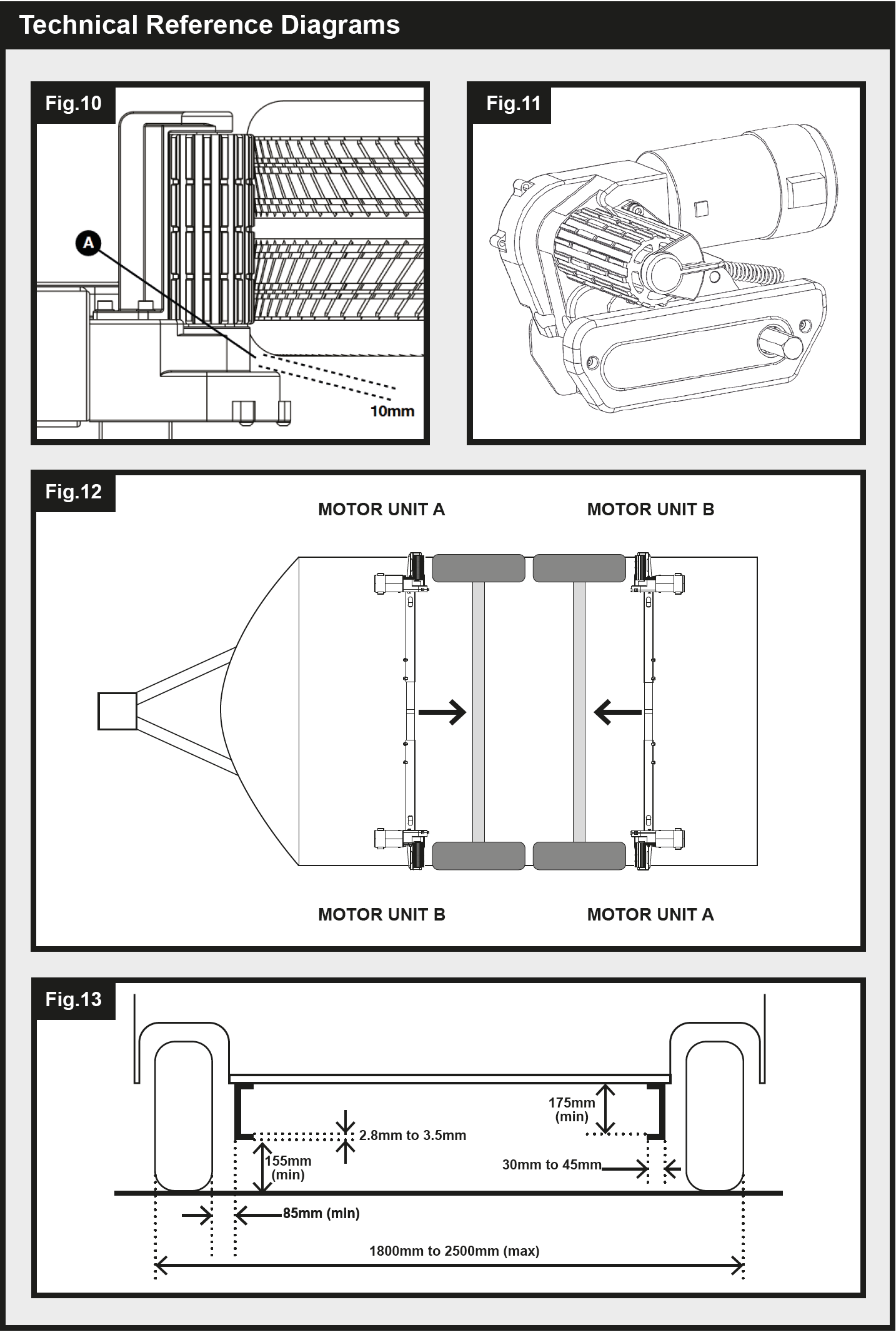
The chassis clamps provided with this system are suitable for fitting onto most standard caravan chassis that have an L-shape or U-shape profile (Fig.11). Please refer to Fig.13 for reference on dimensions and clearances BEFORE you proceed any further with installation. If your chassis has different dimensions to those shown in Fig.13 then various chassis clamp adapters are available to suit the majority of UK and Continental caravans; please refer to the section of this manual entitled ‘Optional Fitting Adapters’.
Specifications
| Model Name | EGO400 – Quattro Titanium |
| Operational Voltage | 12 Volt DC |
| Average Current Consumption * | 25 Ampere (approx) |
| Maximum Current Consumption † | 76 Ampere (approx) |
| Speed | 12cm per second (approx) |
| Approx. Net Weight (inc. all fixings and accessories) | 35kg |
| Safe Working Load (SWL) Twin Motor / Quad Motor | 2250kg / 3500kg |
| Minimum Width (caravan/trailer) | 1800mm |
| Maximum Width (caravan/trailer) | 2500mm |
| Power Source (caravan leisure battery) | 12V |
* Average Current Consumption readings when using an approx. 1100Kg single axle caravan on a hard, level surface.
† Maximum Current Consumption readings when using an approx. 1100Kg single axle caravan ascending a 1:4 (25%) gradient.
Installation Safety Guidelines
Read this User Manual carefully before installation and use. Failure to comply with these rules could result in serious injury or damage to property.
Before starting installation of the caravan mover:
DO check that the caravan is disconnected from the battery supply and the mains electrical supply.
DO only use adapters and accessories that are supplied or recommended by the manufacturer.
DO check that the tyres are not over worn (fitting to new or nearly new tyres is the best option).
DO make sure that the tyre-pressures are correct to the manufacturer’s recommendation.
DO make sure the chassis is in good condition without any damage and is free from rust, dirt etc.
DO stop work immediately if you are in doubt about the assembly or any procedures and consult one of our engineers
DO locate the battery isolation switch to be accessible at all times when parking and moving the caravan.
DO NOT remove, change or alter any parts of the chassis, axle, suspension or brake mechanism.
DO NOT operate the unit if you are under the influence of drugs, alcohol or medication that could impair your ability to use the equipment safely.
These instructions are for general guidance. Installation procedures may vary depending on caravan type.
Use appropriate support! Working under a vehicle without appropriate support is extremely dangerous. If you are fitting the mover system yourself, it is advisable that the installation is conducted by two people, as the mover will need to be raised up to the bottom of the caravan’s chassis before the clamps can be installed.
Remember to complete the product registration form with the serial numbers of each motor assembly prior to fitment (see details within the Guarantee section of this manual).
Installation – Mechanical Components
To begin mechanical installation, ensure that your caravan is placed on a hard, level surface. Where possible the use of a lifting ramp or an assembly pit is ideal for access and personal safety.
Make sure your caravan is prepared for installation. Clean the relevant mounting areas of your chassis to ensure a secure fitting of the mover system. Check before installation that important areas, such as drains, spare tyres etc. do not cause any obstruction to the installation of the mover system and its intended functionality.
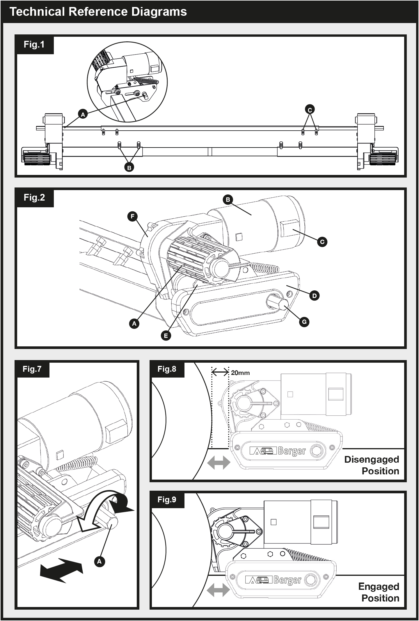
Unpack all of the components and check that all parts are present (see Package Contents Fig.A). The installation instructions will continue to reference the part numbers displayed in Fig.A. Prior to and throughout the installation, ensure that the movers remain in the DISENGAGED position (Fig.8), as the unit will not fit correctly otherwise.
Installation – Classic Clamp System
Loosely assemble motor framework side (1), motor framework side (2) and main cross bar (3) (see Fig.1). The nuts (Fig.1.B) for cross bar fixing must be no more than finger-tight at this stage. Assemble the cross actuation bar by sliding the actuation bars (5) into the actuation centre bar (4) and mount to
the motor assembly rods (Fig.1.A). Fix the actuation bars to these rods using the provided nyloc nut and bolt (pre attached to actuation bars). The nuts (Fig.1.C) for fixing must be no more than fingertight at this stage.
Place the assembly (Fig.1) loosely under the caravan. In principle, the unit should be fitted in front of the caravan road wheels, but if fitting in this position is not possible, it is permissible to fit it to the rear of the wheels by rotating the whole assembly by 180° degrees (note: in this scenario, refer to the rear axle schematic when wiring up your system). Ensure that the Main Cross Bar (3) is positioned in the centre of the caravan/mover assembly (the centre is marked). Adjust the lateral position of each motorside so that the rollers are central to the tyre, or as close to the centre as possible, ensuring 10mm of space is left between the tyre and gearbox of the mover (Fig.10)
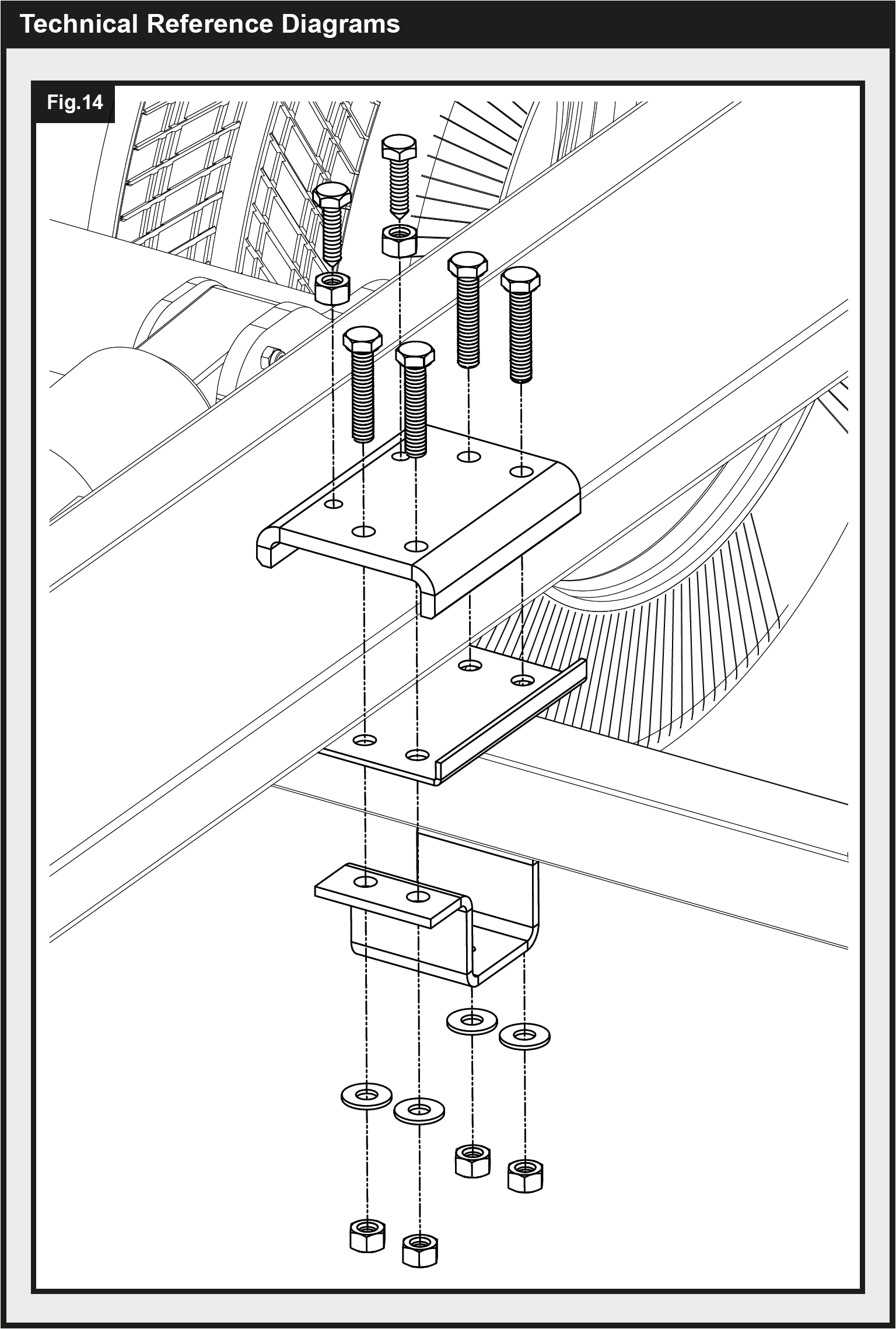
Study Fig.14. On one side of the vehicle, elevate the framework assembly and loosely fit the clamping assembly to the framework and chassis as per Fig.14. Provided clamp fixings (7,16,17,18) must be no more than finger-tight at this stage. Once self supported via the loose fixings, proceed to repeat the process on the other side of the vehicle.
Take due care when elevating and fixing the framework and clamps. Use lifting aids and/or a second persons when lifting/fitting.
With the main assembly loosely fitted onto the chassis, slide the whole assembly along the chassis until the rollers (Fig.2.A) are 20mm away from the surface of the each tyre (Fig.8). Two 20mm spacers (30) are provided to set this distance. Note that the movers should be in the disengaged position when the 20mm spacing is set. When setting the spacing, ensure that the rollers on both movers are centrally in line with the vehicle tyres both horizontally and vertically, to allow for the best possible wheel contact (see Fig.10 for reference). If the roller widths exceed that of the tyre, ensure that the end of the roller is aligned with the outer wall of the tyre. Overhang on the inside wall of the tyre is acceptable on thinner tyres, and should not drastically affect function or grip.
It is important that each roller is at exactly the same distance away from the tyre. The whole assembly must be parallel to the caravan/trailer axle for the system to operate as intended.
Once satisfied with mover spacing, fully tighten the four nyloc nuts (17) on both clamping assemblies (Fig.14) to a torque setting of 40 ft lbs/55Nm, then the bolts (Fig.1.B and Fig.1.C) on each motor side framework to a torque setting of 9ft lbs/12Nm. Re-check the distance of 20mm from the rollers to the tyres and if necessary, loosen the bolts and re-adjust the position of the assembly. Once satisfied with the position of the assembly, fit and tighten the Chassis Stop Nuts & Bolts (7) in each of the Classic Clamp Upper Plates (8) (see Fig.14). Tighten to a torque setting of 40 ft lbs/55Nm. The Stop Bolts grip the lip of the chassis and help prevent the mover from sliding along the chassis.
The main mechanical components have now been installed.
Installation – Shark Clamp System
Loosely assemble the main cross bar (3) inside motor framework side (1) and motor framework side (2) (see Fig.1). The nuts/bolts (Fig.1.B) on the motor frameworks, must be no more than finger-tight at this stage. Assemble the cross actuation bar by sliding the actuation bars (5) into the actuation centre bar (4) and mount to the motor assembly rods (Fig.1.A). Fix the actuation bars to these rods using the provided nyloc nut and bolt (pre attached to actuation bars). The nuts (Fig.1.C) for fixing must be no more than fingertight at this stage.
Place the assembly (Fig.1) loosely under the caravan. In principle, the unit should be fitted in front of the caravan road wheels, but if fitting in this position is not possible, it is permissible to fit it to the rear of the wheels by rotating the whole assembly by 180° degrees.
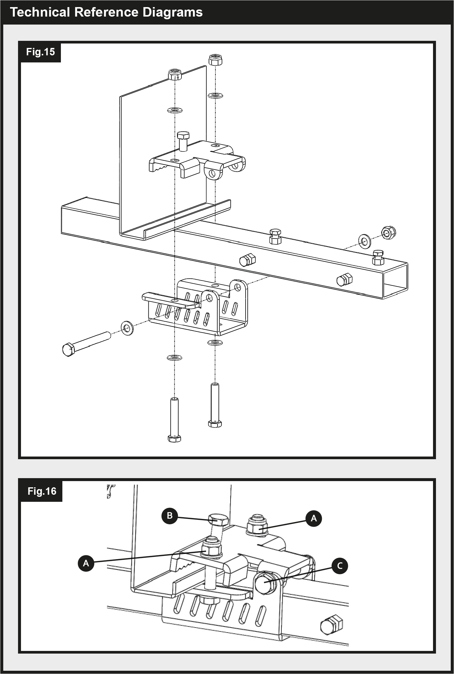
Typically the Shark Clamp will be pre-assembled onto the motorsides for ease of fitting, but if the clamps have been purchased separately or are not pre-assembled, they should be assembled onto the framework as shown in (Fig.15). Before attempting to install the mover onto your caravan chassis ensure that the pinch bolts (Fig.16.B) are removed and put safely to the side.
In turn, open each jaw to its widest position (loosen nuts if required) and hang the motorside framework onto the chassis. If the caravan chassis is a tall U profile, the nuts (Fig.16.B) may need to be removed first to allow the jaws to be opened wide enough.
Loosen the crossbar nuts/bolts (Fig.1B) and adjust the lateral position of each motorside so that the rollers are central to the tyre, or as close to the centre as possible, ensuring 10mm of space is left between the tyre and gearbox of the mover (Fig.10). After adjusting ensure the clamps haven’t moved out of position by holding the framework motorside firmly, while reaching round and pushing the clamps outwards until the fastening bolts and chassis are within 1-2mm of each other. Once happy with the overall width of the mover system, tighten crossbar nuts/bolts (Fig.1.B and Fig.1.C) to 9ft lbs/12Nm to set the width.
Slide the whole assembly along the chassis until the rollers (Fig.2.A) are 20mm away from the surface of the centre each tyre (Fig.8). Two 20mm spacers (30) are provided. Fully tighten the clamp bolts (Fig.16.A) on both clamping assemblies to a torque setting of 40 ft lbs/55Nm. When tightening one clamp bolt, the other may loosen slightly so it may take several passes to get both bolts fully torqued on each clamp. A tip is to do all clamp bolts up until there is a strong resistance before torquing fully.
It is important that each roller is at exactly the same distance away from the tyre. The whole assembly must be parallel to the caravan/trailer axle for the system to operate as intended.
Insert pinch bolt (Fig.16.B) and tighten to a torque setting of 18 ft lbs/25Nm, ensuring while doing this, that the retaining nut is at the highest position. Once the bolt is secure, tighten the retaining nut. Finally tighten the pivot bolt (Fig.16.C) to 9ft lbs/12Nm.
The main mechanical components have now been installed.
Installation – Mechanical Components (AWD Configuration)
To install an All Wheel Drive configuration on your caravan, follow the same instructions outlined in the previous ‘Installation – Mechanical Components’ sections. AWD set up follows the exact same process, with the only difference being the orientation of the movers. In an AWD configuration, the movers powering the rear axle of the vehicle must be orientated facing the front of the trailer (see Fig.12).
Ensure to follow the AWD configuration section of the Electrical/Electronic installation manual closely to ensure that these motor assemblies work as intended and not against one another.
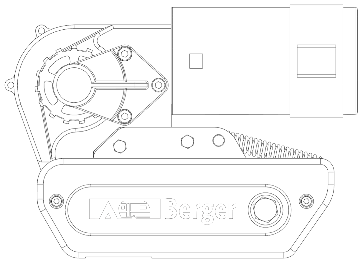
Mover Engagement/Disengagement
With the Rangierhilfe Titanium mover models, the process of engaging is a manual one. To engage your motors, place the engagement tool (6) onto the motor spindle (Fig.2.G) parallel to the ground at a position facing away from the wheel in question. To engage the motor, rotate the engagement tool through 180deg rotating toward the wheel in question (Fig.7). If you cross actuation bars have been mounted correctly, the process of engaging one mover, should subsequently also engage the opposite side of the vehicle.
The engagement mechanism utilises a simple over-centre cam that pushes the rollers onto the tyres and then locks into place automatically. If the mover has been installed correctly, at exactly 20mm away from the tyres when disengaged, the amount of force provided onto the tyre by the roller will be sufficient for most circumstances of use (Fig.9).
Note: Irrespective of which side of the vehicle you are operating the engagement from, the tool should always rotate toward the wheel to engage, and away from the wheel to disengage.
To disengage the rollers, simply refit the tool onto one of the spindles and rotate away from the tyre. Please note that you will feel a small amount of resistance initially as you disengage the cam from its locked position; the spring will then do the rest of the work and pull the roller away from the tyre and into the fully disengaged position (Fig.8).
Installation – Electrical/Electronic Components
Please continue reading below or refer to manual supplied with electronics for wiring installation, operation instructions and troubleshooting.
Maintenance
Please check regularly that the rollers of the drive units are free of any dirt, or debris that may have been picked up during use/during periods of inactivity.
Please check regularly the distance between the rollers and the tyres. In the neutral, fully disengaged
(Fig.8) position this must be 20mm.
Once a year have your caravan movers maintained and visually inspected. This inspection must include all the bolt/nut connections, the cables and electrical connections and lubrication of movable parts/joints.
Long periods of inactivity generate the potential for elements of the movers to cease. Deal with this accordingly by applying lubrication and removing oxidisation where necessary.
DO NOT use any form of pressurised water or chemical cleaning on your caravan movers.
When maintaining your motor mover system, be sure to isolate the electrical supply, failure todo so could result in electrocution.
In case of any failures or problems, please contact your Caravan Mover supplier.
Warranty
Every Berger product is thoroughly checked and tested before it leaves the factory. The warranty is 2 years and begins with the purchase of the device. Please provide proof of this point in time with the purchase receipt (receipt, invoice, delivery note, etc.). Please keep this documentation in a safe place. In the event of repairs, bring the device to your specialist dealer or send it in there.
With the CE mark, Fritz Berger GmbH declares that this product complies with the basic requirements and other relevant provisions of Directive 2014/53 / EU. The declaration of conformity can be requested from info@fritz-berger.de if required.
Only intended for use in dry rooms.
The operating voltage for safety extra-low voltage is a maximum of 50V AC and 120V DC. The protective extra-low voltage protection measure provides protection against direct and indirect contact. Protective extra-low voltage systems are operated without a protective conductor and must not have any connection to the earthed supply network of the protective extra-low voltage generator. Active parts must neither be grounded nor connected to parts with a higher voltage.
Optional Fitting Adapters
Additional chassis clamp adapters shown below are available for purchase:
Low Profile Chassis Adapter Plates (Part No. CM-029)
If your chassis frame height is less than 140mm these plates must be fitted to lower the assembly to provide the correct height of 185mm. Drilling of your chassis may be required. Note: In some countries, the installation must be checked by a professional technician in order to adhere to local regulations.
Narrow Gauge Chassis Adapters (Part No. CM-030)
These plates must be utilised if you have an AL-KO Vario III/AV chassis which has a frame thickness of less than 2.8mm. These must be positioned behind the axle using pre-drilled holes already available on the chassis; so your mover must be fitted behind the axle.
16mm Spacers – 1 pair (Part No. CM-028/Q)
Use spacers to lower the mover assembly if your chassis has a frame height of between 140 to 185mm. A maximum of 3 sets of spacers can be utilised to achieve correct frame height of 185mm. A set of extended clamp bolts must be used in conjunction with these spacers (Part No. CM-031). [For use with Classic Clamp only.]
Set of 8 M10 x 100 Bolts (Part No. CM-031)
Set of 8 extended clamp bolts for use with 16mm spacers. [For use with Classic Clamp only.]
Photographs & diagrams for illustration purposes only. Actual product may differ slightly. All weights & dimensions are approximate. The manufacturer reserves the right to change product specification without prior notice. E & OE.
REMOTE CARAVAN MOVER Electronics Installation Guide and User Manual
Rangierhilfe Titanium CM-071 Basic Electronics
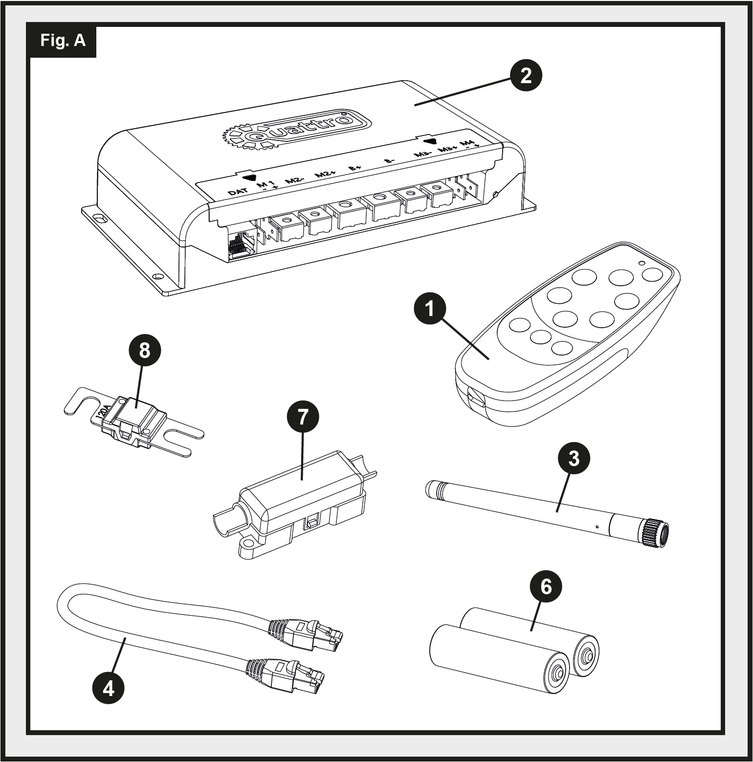
Package Contents (Fig.A)
| Reference | Quantity | Description |
|---|---|---|
| 1 | 1 | Handset |
| 2 | 1 | Electronic Control Unit |
| 3 | 1 | Antenna |
| 4 | 1 | Ethernet Data Cable |
| 5 | 1 | Handset Wrist Strap (Not depicted) |
| 6 | 2 | AAA 1.5V Battery |
| 7 | 1 | In-line Fuse Housing |
| 8 | 1 | 120A Fuse |
Technical Reference Diagrams
Introduction
This manual is a follow on from the installation guide provided with your caravan movers. Please read the installation guide thoroughly prior to attempting anything described in this Electronics installation guide and user manual.
Thank you for choosing these caravan mover electronics. This product has been produced according to high standards and has undergone careful quality control procedures. Simply by using the remote control you can move your caravan effortlessly into any position required within operating guidelines.
Before continuing with installation and starting to use the mover, please read this manual very carefully and be aware of all the safety instructions! The owner of the caravan will always be responsible for correct use. Keep this manual inside your caravan for future reference.
This electronics installation and User Manual covers the steps required to electrically wire your Basic electronics to your given caravan movers. On auto-engage mover models, the remote control handset enables you to simultaneously engage the rollers of movers in any given setup. Once engaged, your handset will allow you full directional control of your caravan, providing accurate manoeuvring and features such as on the spot rotation (single axle mode only).
Installation – Electrical/Electronic Components
This manual is a follow on from the installation guide provided with your caravan movers. Please read the installation guide thoroughly prior to attempting anything described in this Electronics installation guide and user manual.
Several items required for electrical/electronic installation are supplied alongside your motor movers. For reference to these items described in this manual, see the ‘package contents’ section of your installation guide.
Before attempting any electrical work, be sure to isolate the 12V supply from the battery and ensure any 230V electricity supply is disconnected.
Find a suitable place to mount the Electronic Control Unit (2), such as a storage area, under a seat or a bed. Make sure this place is dry and close to the battery (30 cm to 60 cm). Affix the supplied antenna (3) to the rear screw thread at the rear of the electronic control box prior to mounting. The unit can then be mounted on a flat base (horizontal) or on a wall (vertical). When choosing location, ensure that the unit cannot easily be damaged. Fix the Electronic Control Unit (2) into position with four of the screws provided with your mover fixings. If the length of these screws is not suitable for the desired location/material, please substitute as appropriate.
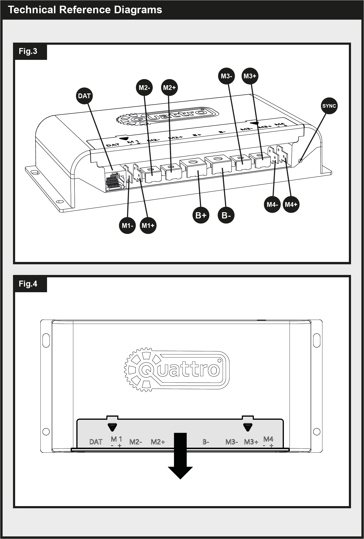
See Fig.4, remove the front cover as indicated. This will allow access to the various terminals on the electronics box. A cross head screwdriver will be required to screw down ring terminal connectors.
Drill a 25mm hole through the floor of the caravan approximately 150mm centrally in front of the control unit (2) terminals.
Take care to avoid any chassis members, gas pipes and electrical wires when drilling the required holes and fixing components to your vehicle.
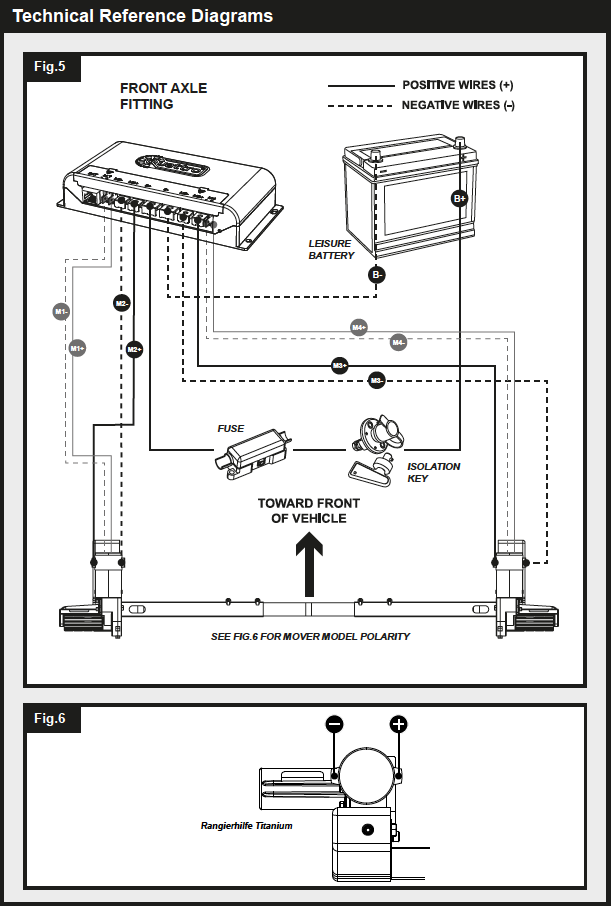
Study Fig.5. The wiring diagram (Fig.5 depicts the wiring route when the motor units are installed on the FRONT wheels/axle, facing the rear of the trailer. Fig.6 displays the polarity of the terminals on the various mover variants. Note that these locations remain the same regardless of whether the motor is the left or right side mover.
Locate the Power Isolation Switch, this will now need to be installed. If available, the ideal location for the isolator switch is inside the battery compartment; usually there is a space to the side of the battery. The chosen location needs to be one that will mean the Isolation switch is easily accessible in the event that the system needs to be switched off in an emergency. Nuts and bolts are provided to mount the switch but please substitute as necessary if they are not of a suitable type for the fitting location or material.
Install the Isolation Switch between the battery and the Control Unit (See Fig.5) along the positive [+] battery cable, using two of the provided 6mm Terminal Ring Connectors to link the cable to the switch terminals. These connectors will require crimping to the end of the wires. Ensure to leave sufficient wire length to reach from the battery to isolation switch and from isolation switch to electronics box.
On the positive [+] battery cable between the isolation switch and electronic control box, the fuse will also need installing. To do this, mount the 120A fuse (8) into the In-line Fuse case (7). Cut the positive [+] battery cable where necessary and again crimp 6mm Terminal Ring Connectors to either end to allow mounting to the fuse. The fuse case (7) can be screwed to a wall or floor in the same way as the electronics control unit.
With the supplied battery wires, proceed to wire the battery to the electronics box, via the previously installed isolation switch and fuse, as outlined in the wiring diagram (Fig.5). 6mm Terminal Ring Connectors are already attached to the battery wires for connection to the electronics box, whilst two sizes of ring connectors are supplied for connection to the battery itself.
Caution! Do not attempt to amend wiring that is connected to the battery and live. Always ensure that wires are disconnected from power when being worked on.
Caution! Ensure not to reverse the positive and negative battery connections. Incorrect connection (reverse polarity) will result in damage to the control box.
The positive and negative motor wires now need connecting to the system, these all feature a pre-installed spade connector at one end of each length. Again using Fig.5 for reference, proceed to route the motor wires through the hole previously drilled in the vehicle floor and along the underside of vehicle toward the designated motors. Supplied are various components which will aid with the safe fixing of these wires, including: Convoluted Cable trunking – to protect the wires from sharp edges, P-clips/screws – for mounting the wires to surfaces, and Cable Ties – to fix wires together or to sections of the chassis where necessary. Cable Number and Polarity markers are also supplied to aid with labelling of wires for ease of installation. When routing the wires, aim to keep these as central along the caravan as possible in attempts to keep the wiring the same length.
As with the battery wires, when satisfied with the routing, proceed to crimp the provided 4mm terminal ring connectors onto the ends of the wires for connection to the electronics box. The spade connectors for attaching to the motors are already fixed to the end of the motor wires.
For Auto-Engage Mover Models the final step will be the attach the engagement wires. These are already wired into your movers, and can be mounted under your caravan alongside the motor wires, again using the supplied mounting components where necessary. Study the various wiring diagrams, the spade connectors attach to locations M1+/- and M4+/- respective of which motor they are from. The positive wire is indicated by a singular white line running down it’s length.
NOTE: Depending on regulatory requirements in your area, it may be necessary to install heavier gauge wiring across the system. Please consult your dealer for further details if necessary.
Once all wires are correctly attached as per Fig.5, the electrical installation is complete.
Installation – Electrical/Electronic Components (AWD Configuration)
To install an All Wheel Drive configuration on your caravan, two separate electronics systems effectively need assembling. These two systems will be configured using the handset prior to initial use, however during installation there are only a few elements which need to be altered.
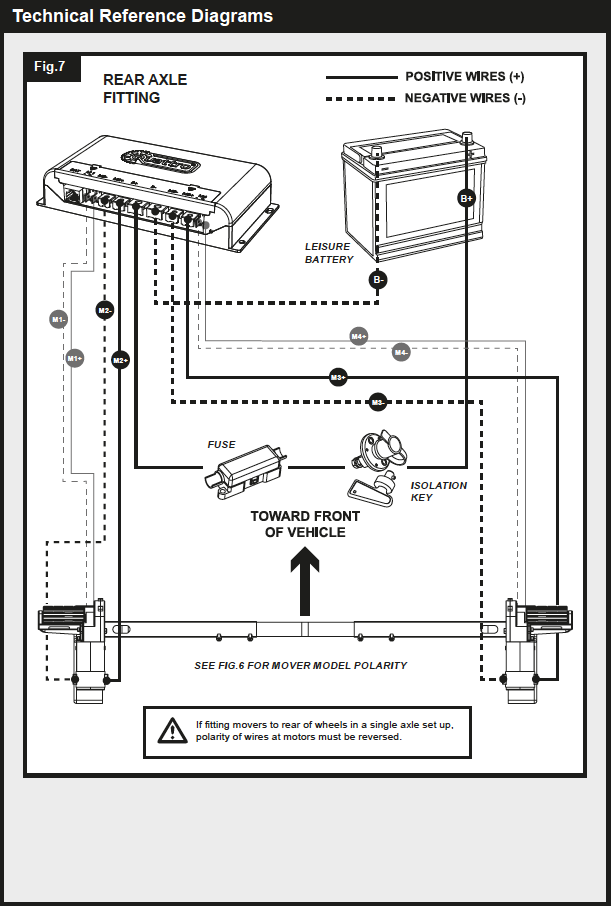
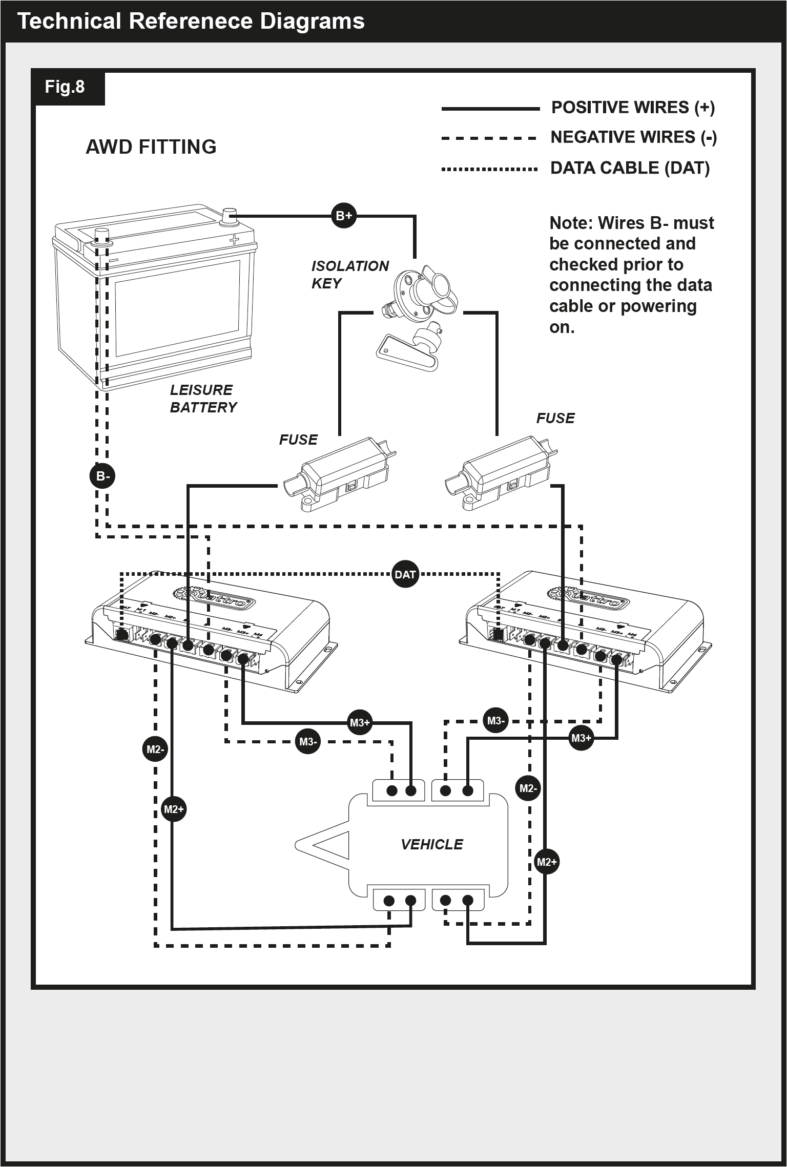
Start by wiring up your second mover system by following the same procedures stated in the previous section ‘Installation – Electrical/Electronic Components’. Fig.7 displays the wiring schematic for this rear axle set up. Fig.8 can also be used for a general overview of how the twin axle wiring should be set up. Follow these diagrams closely to ensure that the movers are powered as intended and do not work against one another in operation.
Regarding the battery wires, the same isolation key can be used for both systems. To do this, connect the second electronics box using a length of wire from the isolation key to the box itself. There should be only a single positive battery wire connected to the battery itself, with two cables then splitting to the respective boxes via in-line fuses from the isolation switch onward. Use Fig.8 for reference.
To finalise the electrical set up, attach the Data Cable (4) between the relevant ports (Fig.3.DAT) in the electronic control units (2). Ensure this is firmly in place.
Follow the ‘Operation – Handset Pairing’ section of this manual closely for instructions on how to set up your remote control to correctly operate the AWD system.
Operation – Safety Guidelines
Caution! Please read these safety guidelines closely BEFORE to attempting to operate your caravan mover system.
DO always check movers for any damage, before use.
DO remain aware, at all times, that ground clearance is reduced by around 50mm where the Movers have been fitted.
DO keep a maximum 5 meter distance between handset and electronics box when in use, to maintain signal strength.
DO be aware that the mover increases your caravan or trailer weight. So this reduces the payload of the caravan.
DO always make sure that the rollers are fully disengaged from the tyres when the mover is not in use. This is better for the tyres and for the mover.
DO always make sure that the rollers are fully disengaged before towing/moving the caravan by vehicle or manpower. If not damage can be caused to your tyres, mover and the towing vehicle.
DO always make sure that after you have finished using the Mover, the Battery Power Isolation Switch is switched off, with the key removed and stored in a safe place, out of reach of children or unauthorised people.
DO always make sure that the remote control handset is stored in a safe place, out of reach of children or unauthorised people.
DO always apply the handbrake after manoeuvring, before disengaging the drive rollers from the tyres.
DO NOT rely on the mover to act as a brake.
DO NOT exceed the stated maximum Safe Working Load (SWL).
DO NOT attempt to move or tow your vehicle with the motor movers engaged on the wheels.
DO NOT make any modifications on the caravan mover (mechanical or electronically). This can be very dangerous! No warranty claim will be accepted and we cannot guarantee the function of the mover if any modifications are made. Purpleline LTD are not liable for any damage whatsoever caused as a result of incorrect installation, operation or modification.
Always ensure that you are close enough to engage the caravan’s handbrake, particularly when manoeuvring on uneven terrain and gradients/slopes, in case of mechanical failure. Do not use the mover as a brake, when you have finished manoeuvring always engage the caravan’s handbrake.
Warning! Ensure that there are no persons or obstructions in the vicinity of the caravan prior to use.
If in doubt regarding any feature of the mover system and its operation, contact your mover dealer.
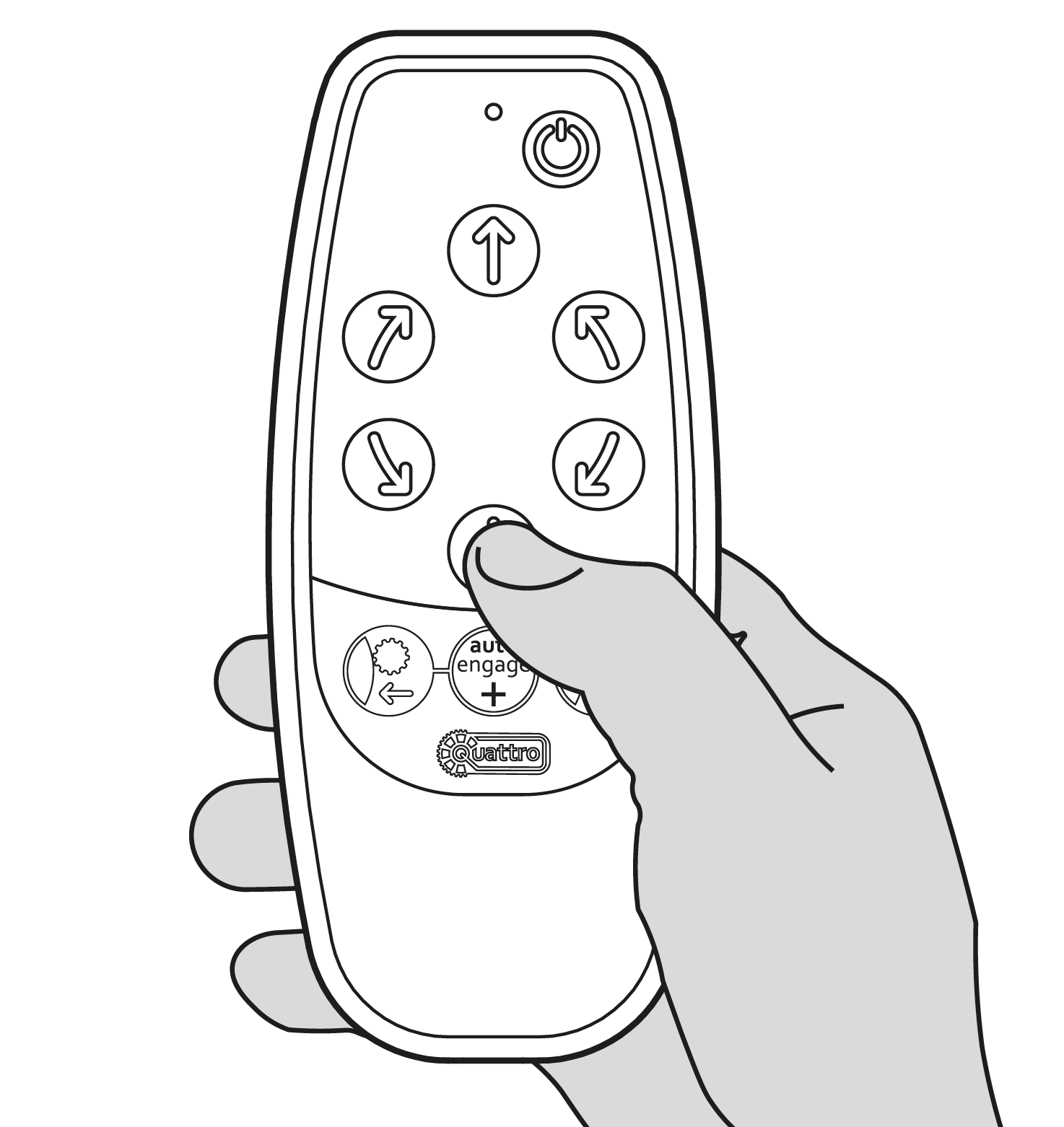
Operation – Handset Functions
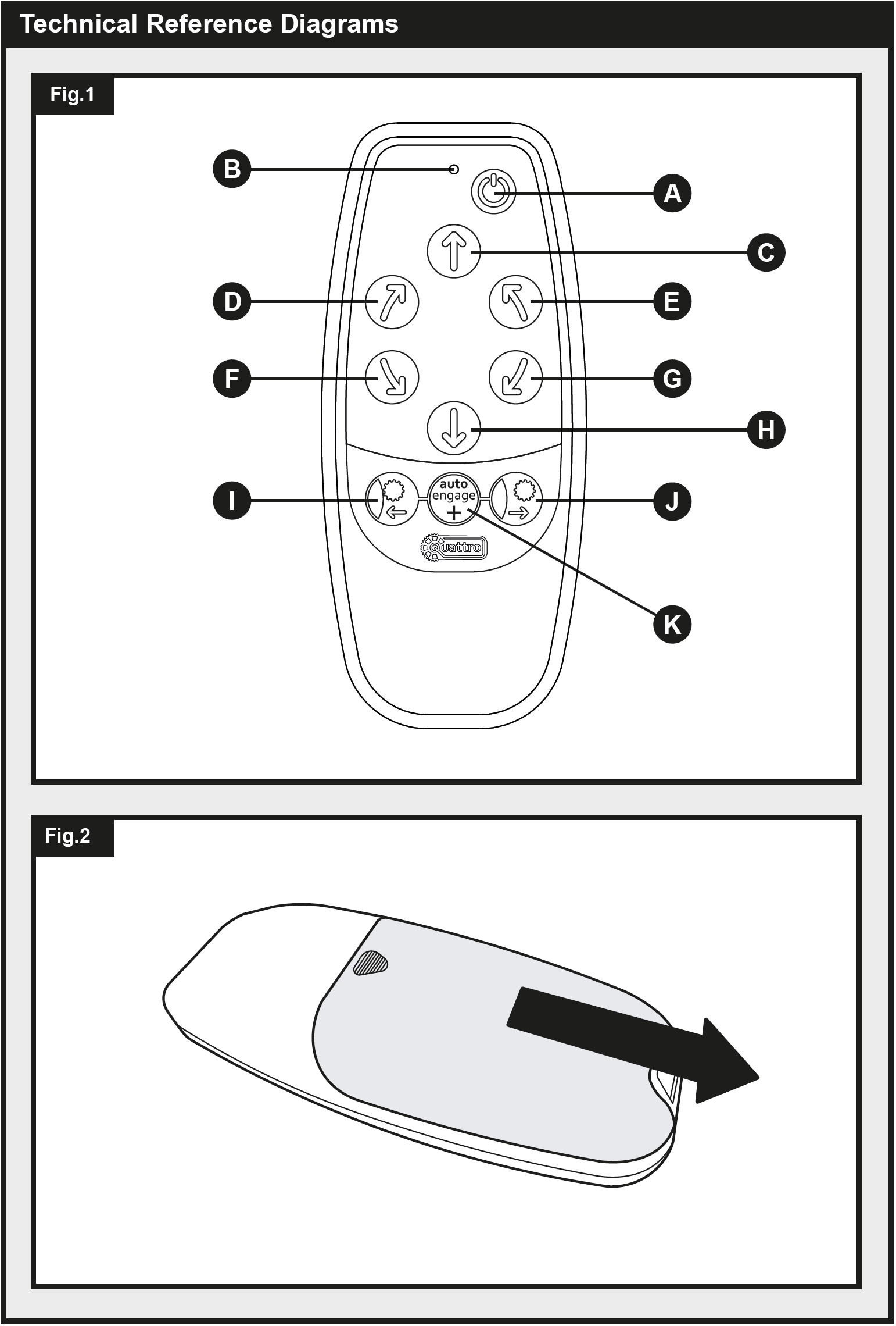
Using Fig.1 for reference, familiarise yourself with the layout of the Remote Control Handset (1).
Power:
Fig.1.A = Power Button (double press)
Fig.1.B = Indication LED
Movement Controls:
Fig.1.C = Forward [F]
Fig.1.D = Forward Right [FR]
Fig.1.E = Forward Left [FL]
Fig.1.F = Reverse Right [RR]
Fig.1.G = Reverse Left [RL]
Fig.1.H = Reverse [R]
Engagement Controls:
Fig.1.I = Engage Button [ENG]
Fig.1.J = Disengage Button [DENG]
Fig.1.K = Auto-Engage Function Button [FN]
The Remote Control handset (1) is powered by two ‘AAA’ 1.5V batteries, to install these, slide off the back case of the handset as seen in Fig.2. Ensure only leak proof batteries are used. Check with local authority regarding the correct disposal of used batteries. Remove batteries from handset during long periods of inactivity.
Double press the power button (Fig.1.A) to turn the handset on. Once activated the LED (Fig.1.B) will illuminate. If the handset has not been used 60 seconds it will power off.
Operation – Handset Pairing / Mode Selection
The handset pairing procedure differs depending on the mover configuration you have installed on your vehicle. It is vitally important that the handset is set up in the correct mode to ensure that the movers operate as intended. With twin-axle vehicles for example, the turning abilities are of course very different to that of a single axle. Only by setting the movers up correctly, will you get the best possible performance out of your mover system.
Familiarise yourself with the handset functions (see ‘Operation – Handset Functions) and electronic control box layout. These will need setting to both the correct model of mover, and the correct mode for your axle configuration. To set the correct model follow the table below:
| Mover Model | Selection Description | Buttons |
|---|---|---|
| EGO400 Rangerhilfe Titanium |
Hold [FN] (Fig.1.K) and[F] (Fig.1.C) for 5 seconds |
To set up the correct mode, see the following sections:
Single Axle Mode
Ensure batteries are installed into the handset as explained in previous section (Operation – Handset functions). Turn on isolation switch to provide power to the electronic control unit (2), a solid red LED will illuminate. Double press the power button (Fig.1.A) to turn on handset.
On your handset (1), press and hold [ENG] (Fig.1.I) and [DENG] (Fig.1.J) for 1 second to enter pairing mode. The indication LED (Fig.1.B) on your handset should continuously flash green. Press the small sync button as shown in Fig.3 on your electronic control unit (2). The LED on this box should quickly flash red, before producing a small clicking noise. The indication LED (Fig.1.B) on your handset should go solid green, and the LED on the electronics control unit (2) change to a slow red flash to indicate the two are paired.
Unless changed, the handset will be in Single Axle mode by default. Where the handset is not in the default mode, press and hold [FL] (Fig.1.E) and [FN] (Fig.1.K) for 5 seconds to select single axle mode. The handset will bleep once to indicate the mode has been set to single axle. Once set, the handset and control box will remember their paring, and will be fully operational simply by powering on.
Pairing Mode:

Single Axle Mode:

Twin Axle Mode (only one driven axle)
Ensure batteries are installed into the handset as explained in previous section (Operation – Handset functions). Turn on isolation switch to provide power to the electronic control unit (2), a solid red LED will illuminate. Double press the power button (Fig.1.A) to turn on handset.
On your handset (1), press and hold [ENG] (Fig.1.I) and [DENG] (Fig.1.J) for 1 second to enter pairing mode. The indication LED (Fig.1.B) on your handset should continuously flash green. Press the small sync button as shown in Fig.3 on your electronic control unit (2). The LED on this box should quickly flash red, before producing a small clicking noise. The indication LED (Fig.1.B) on your handset should go solid green, and the LED on the electronics control unit (2) change to a slow red flash to indicate the two are paired.
The handset will be in Single Axle mode by default. To select Twin axle mode, press and hold [RL] (Fig.1.G) and [FN] (Fig.1.K) for 5 seconds. The handset will bleep once to indicate the mode has been set to Twin axle. Once set, the handset and control box will remember their paring, and will be fully operational simply by powering on.
Pairing Mode:
Single Axle Mode:

AWD Mode (twin axle, both driven)
To configure your system for AWD mode, the handset (1) must be paired with only the front axle electronic control unit (2). To do this, first ensure that as per section ‘Installation – Electrical/Electronic Components (AWD Configuration)’ the data cable (4) is correctly connected to the two control units. Ensure batteries are also installed into the handset as explained in previous section (Operation – Handset functions).
Turn on isolation switch to provide power to both control units, a solid red LED will illuminate on each box. Double press the power button (Fig.1.A) to turn on handset.
On your handset (1), press and hold [ENG] (Fig.1.I) and [DENG] (Fig.1.J) for 1 second to enter pairing mode. The indication LED (Fig.1.B) on your handset should continuously flash green. Press the small sync button as shown in Fig.3 on your FRONT axle electronic control unit (2). The LED on this box should quickly flash red, before producing a small clicking noise. The indication LED (Fig.1.B) on your handset should go solid green, and the LED on the electronics control unit (2) change to a slow red flash to indicate it is paired.
The handset will be in Single Axle mode by default. To select AWD mode, press and hold [RL] (Fig.1.G) and [FN] (Fig.1.K) for 5 seconds to firstly select Twin axle mode. The handset will bleep once to indicate the mode has been set to Twin axle. Once again, press and hold [RL] (Fig.1.G) and [FN] (Fig.1.K) for 5 seconds to select AWD mode. The handset will bleep in a short sequence to indicate AWD mode has been set. LED’s on both electronics control units (2) should now be slowly flashing to indicate they are synced to one another, and the handset (1).
To test the configuration, ensure the movers are all disengaged with no obstructions, hold [F] (Fig.1C). All four rollers should rotate. If no rollers rotate, or only one axle rotates, repeat the AWD setup process, starting will a full reset of your handset (1) as explained in the note below.
Note: For the handset (1) to be paired correctly for AWD, it must have not previously established a connection with either electronic control unit (4). If this is the case, follow the instructions under the Full Handset Reset section of this manual. Turn off your isolation key to cut the power to the electronics control boxes (2). Repeat the AWD pairing process as above.
Pairing Mode:
Single Axle Mode:

Full Handset Reset
There may be scenarios in which you need to cut pairing memory or reset the default settings of your handset. If this is the case, complete a full reset of your handset (1) by holding the power button (Fig.1.A) and [FN] (Fig.1.K) until the handset turns off (around 10 seconds). When your handset is next turned on, the LED will illuminate solid red. Pair your handset as applicable by following the relevant section of this manual, ensuring to select both the mover model and also axle mode.
Full Handset Reset:

Operation – Mover Engagement/Disengagement
Always ensure your caravan handbrake is on before engaging or disengaging the mover system to prevent unwanted movement of the caravan. Only release the handbrake when the movers are securely engaged to the tyres and you are ready to move the caravan.
Automatic Engagement – During transit/installation the engagement motor end block on Auto-Engage movers may rotate causing tightening. Before first use, place the manual engagement tool in the rear of the engagement end block (removing plastic cap) and turn the tool clockwise to ensure it is moving freely, there should be little resistance required to turn the tool.
Warning! When engaging/disengaging, ensure there is nothing obstructing or preventing the movement of the motors. Should the motors stop unexpectedly, check the immediate area for any potential obstructions.
Switch on your isolation key to provide power to your control box. Turn on the handset, a solid green light should indicate that the two are paired, if not, see: Operation – Handset Pairing. For manual engage movers, see the relevant section in the Installation guide. For Auto-Engage Movers:
Engage:
Press and Hold [FN] (Fig.1.K) and [ENG] (Fig.1.I) for 1 second.
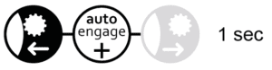
Disengage:
Press and Hold [FN] (Fig.1.K) and [DENG] (Fig.1.J) for 1 second.

Cancel engagement/disengagement:
Press [FN] (Fig.1.K).

Note: During disengagement, the mover will retract from the wheel, make contact with the end of its path of travel, and then proceed to move back toward the wheel for 1 second. This is the prevent long term contact of metal components and will reduce ceasing.
In the event of an issue, an engagement tool is supplied that can be used to manually engage/ disengage auto-engage mover models. To use this remove the small plastic plug on the rear of the engagement motor and turn the engagement worm manually using the tool.
Operation – Manoeuvring
Caution! Please read the operation safety guidelines closely BEFORE to attempting to operate your caravan mover system.
Using Fig.1 and the ‘Operation – Handset Functions’ section of this manual for reference, familiarise yourself with the handset button layout.
Turn on the Battery Power Isolation Switch. Activate the handset by double-clicking the power button (Fig.1.A). The indication LED (Fig.1.B) on the remote control will illuminate. Engage both rollers as described in the ‘Operation – Mover Engagement/Disengagement’ section of this manual. Before operating the Mover, release the handbrake.
Proceed to move the vehicle using the various buttons, ensuring at all times to be aware of your surroundings and terrain. In single axle mode, buttons [FR] (Fig.1.D) and [RL] (Fig.1.G) or [FL] (Fig.1.E) and [RR] (Fig.1.F) can be pushed together to use the spin on the spot function. This feature is disabled in twin axle and AWD modes.
Spin on the spot options:

The mover soft start feature of the motors means that for the first 2.5 seconds, the movers will operate at a lower speed. Note that the general speed can increase a little when going downhill and decrease a little when going uphill. The mover is more efficient when reversing the caravan up an incline.
After manoeuvring, apply the handbrake before disengaging the drive rollers from the tyres. Turn off the system by double-clicking the power button (Fig.1.A) on the remote control. The indication LED (Fig.1.B) on the remote control will turn off. Turn off the Battery Power Isolation Switch to cut power to the electronics control box(es).
Store remote control and isolation key in a safe place (out of reach of children or other unauthorised people).
Some mover models have a regenerative braking feature that allows full directional control to be maintained while moving downhill. This is achieved by feeding energy under braking back from the motors into the battery. Some lithium leisure batteries do not allow this and when an incompatible battery is detected, the feature will be automatically disabled within software to prevent damage. Therefore, when moving down an incline with an unsupported battery, manoeuvring is limited. To ensure the best performance and compatibility on a lithium battery we recommend only using approved batteries.
When manoeuvring is complete, ensure to apply your vehicle hand break prior to disengaging your movers or turning off your electronics unit or handset. Never rely on the movers to act as a break.
Hitching and Unhitching
It is possible to position the caravan’s hitch exactly over a stationery car’s tow ball using the mover system, however this should be done with caution.
Use the movement buttons on the remote control to bring the caravan to the car. It is better to reach the tow ball with several short “trips” rather than trying to do it in one “trip”. When the hitch is right above the tow ball of the vehicle, lower the hitch to the ball and engage in the normal way using the jockey wheel. Hitch the caravan as you would for normal towing. Disengage the movers from the caravan’s tyres (see Operation – Mover Engagement/Disengagement).
Do not attempt to tow your vehicle with the Movers engaged! Make sure that both rollers are fully disengaged. Trying to drive away with the mover still engaged, will damage the mover, your caravan tyres and strain your tow vehicle!
Maintenance
To prevent your leisure battery from becoming totally discharged during long periods of inactivity it must be disconnected and recharged before using again.
Please check regularly that the rollers of the drive units are free of any dirt, or debris that may have been picked up during use/during periods of inactivity.
Please check regularly the distance between the rollers and the tyres. In the neutral, fully disengaged position this must be 20mm.
When your caravan is stored for an extended period of time (over winter for example) it is recommended to remove the leisure battery from the caravan. Make sure you keep it charged to ensure it is in good condition the next time you want to use it.
Once a year have your caravan movers maintained and visually inspected. This inspection must include all the bolt/nut connections, the cables and electrical connections and lubrication of movable parts/joints.
It is advised that you regularly check that no wiring connections have come loose across your motor mover system.
Long periods of inactivity generate the potential for elements of the movers to cease. Deal with this accordingly by applying lubrication and removing oxidisation where necessary.
DO NOT use any form of pressurised water or chemical cleaning on your caravan movers.
When maintaining your motor mover system, be sure to isolate the electrical supply, failure to do so could result in electrocution.
In case of any failures or problems, please contact your Caravan Mover supplier.
Troubleshooting
Unit fails to operate or moves intermittently. Possible solutions are:
Handset not paired – Your electronic control unit LED will feature a slow constant red flash, and your handset LED a solid Green light to indicate connection. If this is not the case, follow relevant pairing instructions in the ‘Operation – Handset pairing / Mode Selection’ section of this manual.
Handset not turning on – Handset battery could be depleted. If empty, renew using two new ‘AAA’ 1.5V batteries.
Caravan battery low/empty – Check that the leisure battery is fully charged using a voltmeter. To operate effectively, the voltage of your battery should be at a minimum of around 12.8V.
Motor cable issue – Check all connections between motor cables and control unit to ensure theses have not come loose or detached.
Battery cable issue – Check battery terminals, clean and connect again.
Low signal – before operating the mover ensure that the signal between the control box and handset is good. Your electronic control unit LED will feature a slow constant red flash, and your handset LED a solid Green light to indicate connection. Ensure your aerial (3) is correctly connected and the distance between the handset and control unit is no greater than 5m during use.
Handset modes not correctly set – In certain circumstances, the system will not operate if the correct modes have not been set. Follow the ‘Operation – Handset pairing / Mode Selection’ section of this manual.
Rollers slip on wheels – Check that the disengaged distance of the rollers to the tyres is 20mm on both sides. Check for correct tyre pressure by referring to your caravan manufacturer’s handbook. If the pressure is low, the roller would need to be pushed into the tyre further than usual to gain sufficient traction.
Rollers not engaging/disengaging (Auto-Engage Models) – Check the polarity of your engagement wiring (refer to relevant wiring diagrams). If the motor functions but stops short, ensure firstly that nothing is obstructing any given motor. Where necessary, lubricate the mover and framework to prevent ceasing.
Indiction LEDs
Note Indication LEDs on both your handset and electronics control unit(s). The following guide can be used for reference:
Handset:
| LED Status | Meaning |
|---|---|
| OFF | Handset Off or not receiving power. |
| RED/GREEN Flash | Attempting to pair to a previously established connection. |
| GREEN Flash | Pairing mode, attempting to establish new connection. |
| Signal received, system in Operation. | |
| RED Solid-Flash-Solid (accompanied by alarm) |
System error: During set up – Handset has likely been incorrectly set to AWD mode (or data cable not properly connected, if AWD mode was intended) During Use – Refer to System Errors table. |
| Solid GREEN | On and Paired with control box. |
| Solid RED | Handset fully reset, all modes set to default |
Electronics Control Box:
| LED Status | Meaning |
|---|---|
| OFF | Handset Off or not receiving power. |
| Solid RED | Attempting to pair to a previously established connection. |
| Fast RED Flash | Signal received, system in Operation. |
| Slow RED Flash | Paired with handset, awaiting commands. |
| RED Solid-Flash-Solid (accompanied by alarm) |
Refer to System Errors Table. |
System Errors
System errors can occur for numerous reasons. If persistent, contact your caravan mover dealer. Use the table below for reference and troubleshooting.
In any given LED indication, errors will be stated in the following way:
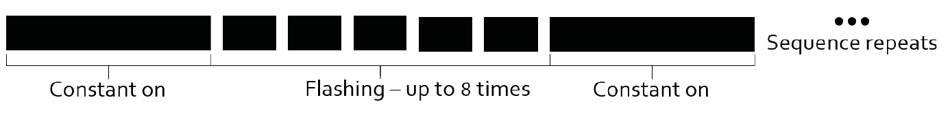
All system errors are accompanied by an alarm from the handset, this will clear alongside the flashing after around 8 seconds, or until the error has corrected. Various errors are listed below:
| (RED) LED Status | Description | Possible Cause and Action |
|---|---|---|
| 2 flashes | Over Current (Motor) | Usually caused by overworking system, avoid excess load or steep slopes, check vehicle brakes are not engaged. |
| Over Current (Battery) | ||
| 3 flashes | Under Voltage | Usually caused by a low/flat battery, check voltage. |
| 4 flashes | Over Voltage | Usually caused by an incompatible battery, or when a charging system is in place whilst operating. |
| 5 flashes | Over Temperature | Usually caused by prolonged use on a heavy load. – Allow 5 minutes for electronics to cool down. – Break long periods of travel into shorter ‘trips’. |
| 6 flashes | Critical Low Voltage Lockout | Usually caused by a loose or dry connection in wiring or use of an end of life battery. – Ensure system is powered off, Check wiring and terminal condition. – Verify battery condition through proper means (do not rely on internal caravan battery monitor). |
| 8 flashes |
M2 Motor Driver Failure M3 Motor Driver Failure M2 and M3 Motor Driver Failure |
Triggered when output voltage is not detected: – Possible short circuit on the motor. – Possible controller failure.Cycle power, if problem persists, do not use again and contact dealer for support. |
Photographs & diagrams for illustration purposes only. Actual product may differ slightly. All weights & dimensions are approximate. The manufacturer reserves the right to change product specification without prior notice. E & OE.